Wire Bonder
Wire Bonder | Contact Information |
| Model: MEI 1204W | Faculty Contact: Aaron Hawkins |
| Company: Marpet Enterprises Inc. | Staff Contact: Jim Fraser |
| Maintenance Request | Student Contact: Eric Christie |
| SCHEDULER IS REQUIRED |
General Information
Operating Procedure
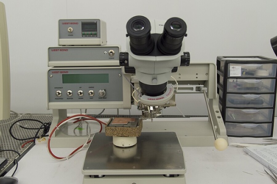
The wirebonder is designed for ultrasonic, thermosonic, or thermocompression wedge bonding of IC's, hybrids, microwave devices, and laser diodes using gold or aluminum wire from .5 mil (12.5 microns) to 3 mil (76 microns) and ribbon.
Ensure the bonding tool(needle) is threaded properly.
- The gold/aluminum wire should be coming off of the top of the spool and not the bottom.
- The thread should enter the transducer arm in the first hole available after the spool mount.
- After passing through the transducer arm the wire should be threaded through the eye hole on the clamp and cross the clamp pad--the outer clamp must be removed for this process(be gentle, the quartz pad may break off the clamp casing).
- From this point it should go through the bond tool(needle).
- Pull extra wire through the bond tool to ensure it feeds through very smoothly and replace the outer clamp.
- If there are questions about needle threading please see those in charge of the bonder.

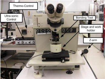
Picture of bonding tool
Assuming that the machine is calibrated correctly and the bond tool is properly mounted and threaded, the basic operation of the wire bonder is as follows.
- Mounting your sample:
- Mount you sample on the work holder and clamp it, then set the height of the surface to be bonded to 3-3.2 inches using calipers. This can be done by loosening the set screw on the side fo the work holder and hex screw on the underside of the work holder.
- Turn on bonder:
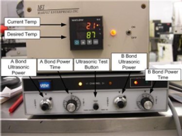
- Turn on the bonder and ultrasonic control (and the heated stage if desired). Then check the bonding parameters (temperature, power and time on channels 1 and 2 of the thermosonic controls).
- Picture of wirebonder controls
- Bonding:
- After properly loading the sample on the work holder and setting the height, place the work holder on the stage and look through the microscope to position the part to make the first bond using the micro-positioner. Lower the Z-arm(located on the lower right side of the machine. This allows the operator to have direct control of theup and down motion of the machine durning the bonding process) until the bonding tool contacts the part. Continue down with the Z-arm until you hear the machine cycle(the machine takes care of the force applied -so be gentle-, extra force applied at the Z-arm does NOT translate into additional bond force or power). Once the ultra-sonics have fired, gently raise the Z-arm for the 2nd bond.
- Move the part to the desired location to make the second bond, using the micro-positioner. Gently lower the Z-arm again, which will trigger the ultra-sonics at the end of its stroke. The Z-arm triggers the logic cycle on the machine by using sensors... so AGAIN, the operator should not use much force to move the Z-arm. Bond head speed is controlled by the damper, and is independant of the speed the Z-arm is moved. This provides a uniform force for bonding.
- After making the second bond release the Z-arm and proper operation of the machine will allow the wire to break and leave sufficient wire to continue onto the next bond.
- For proper bonding, the transition direction from the 1st bond to the 2nd bond should be exclusively along the y-axis. Veering to the left or right (along the x-axis) between the 1st and 2nd bonds will cause the wire to fall off the bonding tool's foot and prevent a proper 2nd bond from being achieved.
- If bonds are not sticking attempt to adjust the following:
- Bond force
- Ultrasonic power level
- Application time of ultrasonic pulse
- If you feel it is necessary to adjust the A-search, B-search, Loop or Reset knobs please consult those that are in charge of the wirebonder before proceeding.
- Other notes:
- Switches, knobs and buttons not specifically outlined above should be left alone without proper training or consulting those in charge of the bonder. Also, do not attemp to calibrate without consulting those in charge of the bonder.
- The 'Test' button on the ultrasonic controls outputs full ultrasonic power to the bond tool as long as it is pressed. As a rule this shouldn't be used as a means of completing bonds due to wear and tear on the bond tool(needle). it shouldn't be necessary under proper operation of the wirebonder. Use sparingly (or not at all) because it isn't the intent of the TEST button. It is merely there to test the proper operation of the ultrasonics.
- Sign the Log and note all anomalies.