PlasmaTherm 2

PlasmaLab Model DP800 | Contact Information |
| Maintenance Request | Faculty Contact: Aaron Hawkins |
| SCHEDULER IS REQUIRED | Staff Contact: Jim Fraser |
| Student Contact: none |
The Plasma Enhanced Chemical Vapor Deposition (PECVD) 2 machine is used to deposit thin dielectric films. It combines up to four gases at pressures between 0.1 and 2 Torr and uses an RF source of up to 600 Watts (total power 650 W) to ionize the resultant gas mixture, causing film deposition on a heated substrate (250-300°C). Films that can be deposited with the system include: SiO2, SiOxNy, and SiN. Currently, PECVD2 is only used to deposit SiO2. Dr. Hawkins must approve any use of PECVD 2. PECVD allows us to deposit good-quality films at low temperatures (250-300°C). However, these films are inferior to thermal CVD films in several ways: PECVD oxide is amorphous and non-stoichiometric. This means that instead of growing stoichiometric SiO2, what really is deposited is SiOxHy, with the hydrogen coming from the precursor gas silane. Because of this, the film has lower density than thermally grown SiO2. PECVD oxide is not as good an electrical insulator as thermal oxide. PECVD oxide is physically rougher than some other oxides. PECVD oxide can be deposited with a refractive index from 1.45-1.47.
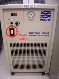
Starting up the necessary equipment 1. The process gases include 5% silane in helium (SiH4/He), nitrous oxide (N2O), and halocarbon cleaning gas (20% O2 in CF4). The tanks are located in the gas cabinet adjacent to the cleanroom. To turn on the 5% silane, twist the red shutoff button on the control panel clockwise until it pops up, then press the "START" button. The CF4 and N2O are not run through the control panel of the gas cabinet. The CF4 must be turned on and off using the valve on top of the cylinder next to the cabinet. The N2O should always be turned on. 2. The chiller located on the floor next to the PECVD2 must be turned on anytime the substrate heater is on. The chiller should not be turned off until the plate has cooled to at least 100°C. Flip the chiller's power switch to "on".
Depositing Oxide 1. Set/Verify your parameters To change gas flow rates, RF power, or process pressure, turn the key to the "CHANGE STORED PARAMETER" position. To verify any parameter, hold the "READ" button and select the parameter you want to verify. To change a parameter, hold the "SET" button and select the parameter you want to set. You will use the numeric keypad to enter the value you want to set, and then press the "STEP/ENTER" button to enter the value. The settings for the gas flows and the RF power are in percentages, while the process pressure is absolute and in Torr. GAS 1 - Silane (5% SiH4 in He) 1000 SCCM, calibrated with H2 GAS 2 - Nitrous Oxide (N20) 200 SCCM, calibrated with N2O GAS 3 - Ammonia (NH3) 100 SCCM, calibrated with NH3 (Not used at this time.) GAS 4 - Halocarbon (20% O2 in CF4) 1000 SCCM, calibrated with N2 When you are finished changing parameters, turn the key back to "MANUAL OPERATION" 2. Turn on the substrate heater by pressing the up arrow on the Watlow temperature controller until the set point (red numbers) reaches the desired temperature. It will take about an hour to reach 250°C, so it is a good idea to open the chamber and inspect the chamber condition when you turn the heater on. If the chamber is dirty, use the heating-up time to clean. 3. With the plate heated up to the process temperature and the gas flow rates, the throttle pressure, and the RF power level set, you are ready to deposit oxide. It is recommended to run an oxide plasma at the normal process conditions for 10 minutes before attempting to grow on your wafers. This helps to stabilize the deposition rate and cleans any dust out of the showerhead. 4. Vent the chamber by holding "MANUAL" and pressing "VENT" and wait until the light stays on. 5. Open the chamber with the access levers a. Left Lever - Controls the speed the chamber is raised and lowered. To the left is stop, right is go. b. Right Lever - Raises and lowers the chamber. To the left is down, right is up. 6. Place your wafer(s) on the center of the hot plate, surround your wafer with spacer wafers, and then close the chamber with the levers. 7. Pump down the chamber by holding "MANUAL" and pressing "ROUGH". Wait until the lights for "ROUGH" and "HI-VAC" stop blinking. 8. Turn on the gases and throttle valve by holding "MANUAL" and pressing "GAS 1", "GAS 2", and "THROTTLE". 9. Wait for the pressure to stabilize - it usually stabilizes at around 0.025 Torr above the set pressure. 10. Strike a plasma by holding "MANUAL" and pressing "RF". The plasma will take a second or two to strike, so don't start your timer until you see the plasma through the window. If the plasma does not strike, or dies after striking, try increasing the RF power level. 11. When finished, turn off the plasma by holding "MANUAL" and pressing "RF". Turn off the gases and the throttle in the same way and vent the chamber (step 3.) 12. Remove your wafer(s) and all spacer wafers. 13. Perform a CF4 clean for at least 3/4 of your oxide deposition time. Shutting down the PECVD2 1. Turn off the heater by setting the temperature to 0 on the temperature controller. 2. Pump down the chamber by holding "MANUAL" and pressing "ROUGH." 3. Close the cutoff valve behind the machine. 4. Make sure to turn off all gases that were used. Shut off the silane by pushing the red button on the gas cabinet controller. Close the valve on the top of the CF4 cylinder. The N2O is not shut off. 5. Only turn off the chiller if the plate is under 100°C. Turn off the chiller by flipping the power switch to off. 6. Don't forget to sign the log book!
Cleaning Instructions
Things to remember: NO WATER ALLOWED - do not spray water anywhere inside the chamber. DO NOT TOUCH THE HOT PLATE with your gloves, the vacuum, or anything else (besides clean wafers) when it is hot. In addition to being a safety hazard, you will contaminate the plate with carbon residue that will affect subsequent growth. If this happens, perform a CF4 clean until the residue is gone. Clean the outside of the machine. Wipe down the outside of the chamber and the counter behind the lid. CF4 Clean - must be done after every deposition to clean the hot plate and showerhead. Vacuum the showerhead. This should remove most of the particulate matter. Be careful not to touch the hot plate with the vacuum hose or your gloves. Use cleanroom wipes moistened with isopropyl alcohol to wipe down the showerhead. Also, wipe out the window on the side of the chamber. Wipe the base plate and the center plate if it is not hot. Use the nitrogen gun to blow off the hot plate and the base plate (below the hot plate). Close the lid and pump down the chamber. Use cleanroom wipes and the nitrogen gun to clean off the outer surfaces of the PECVD. There should not be any visible dust anywhere on the machine. Run a CF4 cleaning process for at least 3/4 of the oxide deposition time or until there is no white residue on the hot plate or the showerhead.
Process Recipes
MFC Flow Rates To determine the flow for each gas, multiply the percentage by the full flow in sccm Gas 1 (SiH4) : 1320 sccm Gas 2 (N2O) : 200 sccm Gas 3 (NH3) : 100 sccm Gas 4 (CF4/20% O2) : 482 sccm 250°C Oxide Recipe (~3.0 μm/hour or ~50 nm/min) - Good Uniformity GAS 1 (silane) - 9% GAS 2 (nitrous Oxide) - 17% Throttle Pressure - 600 mTorr RF Power - 3% 250°C Oxide Recipe (~3.0 μm/hour or ~50 nm/min) - Good Conformality GAS 1 (silane) - 10.5% GAS 2 (nitrous Oxide) - 14% Throttle Pressure - 1100 mTorr RF Power - 3% CF4 Cleaning Recipe GAS 4 (CF4) - 30% Throttle Pressure - 600 mTorr RF Power - 18% (Decrease if temperature goes up)


Chamber Characterization The index of refraction, film stress, and deposition rate were measured when varying the ratio of SiH4 and N20 and are found on the graphs below. The base recipe was 16 watts, 164 sccm Silane/Argon, 88 sccm N20, 1900 mT, and 250 C. This is a SiH4/N20 ratio of 0.093.


CF4 Characterization The index of refraction, film stress, and deposition rate were measured when varying the amount of CF4 added to a run and are found on the graphs below. The base recipe was 16 watts, 164 sccm Silane/Argon, 88 sccm N20, 1900 mT, and 250 C.