Automatic Dicing Saw

Disco DAD 320 | Contact Information |
| Maintenance Request | Faculty Contact: Aaron Hawkins |
| Staff Contact: Jim Fraser | |
| Student Contact: Kolby Smith |
NOTE:
- Users must purchase their own blade for the machine
- Questions: Contact the student contact first before going to the Staff or Faculty contact
A Dicing Saw is used to cut(or dice) or groove semiconductor wafer into small square, or die. The Dicing saw is equiped with a high speed spindle with an ultra thin diamond blade (or diamond saw) to dice the wafer into particular sizes. The image below describe the general purpose of the dicing saw:(image source from www.disco.co.jp)
Information about diamond blades
A typical blade number is 27HEEE. Only 27H blades should be used on the machine unless your lab has an established record of using another blade. 27H specifies the inner diameter and outer diameter of the blade. The three letters following the H specify the cutting grit, the blade exposure, and the kerf width. Typically, only grit E blades have been used on the machine. It is possible that other grits may be used but do so at your own risk. The second letter specifies the blade exposure which is the distance radially which the diamond blade extends from the aluminum hub. Typically, an exposure E blade is used on our machine. The final letter specifies the kerf width of the blade cut. This is the thickness of the cut which the blade makes. Typically a kerf width E or F is used. Cutting blades are not available to purchase through the EE shop. Search for disco dicing blades online.
Operating Instructions
- Assure necessary equipment is on and install blade
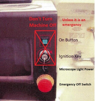
- Leave the machine on at all times. The backup battery is not functioning properly. If the machine is turned off, the machine memory may fail requiring an expensive repair. See Figure 2 for the on button, the ignition key and the emergency off switch which should not be touched unless it is a real emergency (i.e. the blade is cutting the chuck or someone is being injured).
- Make sure the air and the water are turned on. The air and water are on when the valves are rotated completely counterclockwise. These are found to the right of the machine, and the valves are shown in Figure 3. If the air is not on, the spindle air bearing will fail causing severe damage to the machine when the bearing grinds. The water cools machine components and the blade. THE AIR AND WATER SHOULD BE LEFT ON AT ALL TIMES.
- Turn on the monitor. The power button is found behind the glass and machine frame at the bottom right of the screen.
- Turn on the microscope light by turning the black knob between the emergency off switch and the ignition key clockwise.
- The Main Menu screen should be displayed. If not, press the exit key (E1) until it is displayed.
- Check your blade for any chips or defects along the diamond cutting edge. If you find any, you need to purchase a new blade.
- Remove the water manifold or rotate bar to access the spindle. Refer to Figure 4.
- Remove the blade retaining nut using the orange handled Allen wrench and nut turning jig (see Figure 5) stored in the box on the table opposite the machine. For best operation, hold the jig still after inserting the pins in the holes of the blade retaining nut. Rotate Allen wrench according the right hand rule. Install your blade. Replace the blade retaining nut and tighten.
- If you removed the water manifold or moved the bar while installing the blade be sure to reinstall the water manifold. Rotate the bar so that it is approximately parallel with the blade and not touching. Be sure to not touch the water nozzle. Check that the water jet is spraying on the blade by pressing the Cut Water (J4). The jet should split across the blade.


The Key Panel:
Most of the interaction with the dicing saw is done through the key pad shown in Figure 6 below. For convenience, a coordinate system was placed on the top and left of the keypad so that the position of the keys can be easily described in these instructions for example; the "7" key would be denoted as 7 key (Al).

Initialization and Setup
WARNING: If the following steps are not followed, the machine will not initialize properly, and the blade may explode upon contact with the wafer chuck.
- Press the SYS INIT key (H4). The machine will then run through some automatic adjustments and checks. Once finished, the screen will display "Initialization Completed" in the bottom left corner of the screen.
- Starting at the main menu. Press F5 to enter the Blade Data Maintenance menu. Press F1 to perform a Blade Exchange. Verify the blade number is the same as the installed blade. Typically a 27HEEF or 27HEEE is used.
- If not, select the appropriate blade from the list by pressing F5 and scrolling through the list using the gray arrow keys. Press Enter (C4) to store data. The unit system for the blade data may also be changed at this point.
- Press the SET UP key (H3). The setup screen should appear. Verify the Blade O.D. is 2.18700 inch and the Chuck Table Size is 6 inch, then press the Enter key (C4). The chuck table will begin to translate and rotate. The spindle will turn on. The blade will lower until it contacts the chuck table completing an electric connection between the blade and the chuck. This allows the machine to locate the blade edge relative to the chuck.In the unlikely case the blade begins to cut the chuck, press the Emergency Off Switch and talk to the student contact as soon as possible.
- If there is an error in the setup process, the machine will not run. Possible causes of an error may include a chipped and/or unclean blade.
- In the event of a chipped blade, the blade will need to be replaced following the procedures listed in this instruction page.
- If the blade is not chipped try running the water for a moment by pressing the Water key (J4) and then run the setup again from the beginning.
- If neither of these solutions works, refer to the user's manual or seek help from the student contact.
- Press the Exit key (E1) three times.
- The Main Menu screen should be displayed. Setting Device Data.
- From the main menu, press the F3 key (J1) to go to the Device Data List.
- Enter the data number (100 for silicon and 102 for glass) in the "Select Device Data" field and then press Enter (C4).
- The Device Data (1) screen should then appear.
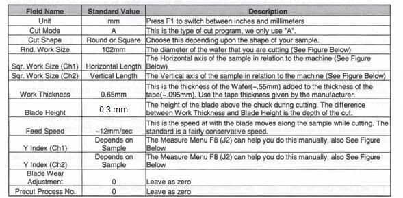
- The Dicing Saw Program Table, Table 1, shows the Field Name, and the corresponding standard value for the field.
- Go through each item and make sure that they are correct.
- The blade does not need to cut completely through the wafer. In fact, this is undesirable because it increases the chance that the blade will come in contact with the chuck and chip. Users have found that a blade height of 0.3 mm is a good place to start. Make a cut on a junk piece of wafer and see if it cleaves well. If it does not, decrease the blade height. A blade height of 0.2 mm has been used safely several times. Do so at your own risk.
- See Figure 7 for a schematic showing round work and square work sizes.

20. Y-Index The Y index will be the distance between each cut if multiple cuts are made. If that is not predetermined, this parameter can be used to jump a specified distance on the screen to make aligning the cut a little easier. The channel 1 Y index is the distance between cuts before a 90 degree rotation. Channel 2 Y index is the distance between cuts after a 90 degree rotation.
Installing Wafer on Chuck
21. Apply adhesive plastic to positioned wafer and metal ring using the dispenser made by USI Ultron Systems. It is located adjacent to the acid cabinet on the left.
22. Put the side of the wafer you wish to align to face down on the green plastic with the flats aligned with the indentations. Place the metal ring so that the notches align with the two protruding silver pins. It may be installed with the narrow notch on either the left or right. Refer to Figure 8.

23. The cutting blade on the dispenser is dull. Use a razor blade to cut along the same line where the dispenser's blade would cut. Notify the student contact if the plastic roll is running low.
24. Take the plastic adhered ring and wafer to the glass table opposite the dicing machine. Use a razor blade to cut plastic along the outer edge of metal ring. It is not critical to cut out the two small notches.
25. The sample must be vacuumed down on the chuck, so the C/T Vac key (L4) must be pressed. This key is quite worn on our particular machine.
26. Press it and the vacuum gauge should show that it is under vacuum. Figure 9 shows the vacuum gauge is the spin dial with green and red regions located at the top left side of the machine next to the water flow rotameters.

Making Cuts in Semi-Auto Mode
- s_auto from the Device Data Screen. This is done by pressing the F7 key (I2).
- A different screen should appear displaying two microscope images of the surface similar to the aligners for photolithography. The microscope light may be adjusted with the black knob. The focus may be adjusted with the silver dial on the left side of the microscope fixture. Using the x, y, and theta keys, align the wafer to be cut.
- The dotted lines across the screen may be used to align the angle, however as the blade isn't spaced properly they do not indicate the location of the cut.
- Here are some unconfirmed recommendations for improving the accuracy of your cut from the previous version of the instructions. For an approximate location, the top of the screen can be used for alignment. For a precise cut, set both of the Y index values to .2546 and then on the screen, align the cut location to the middle line and move one index down so that now your cut location is near the top of the screen, and you will get an accurate cut. For precise cuts, you will be unable to make more than one cut at a time as you will need to align each manually.
- Once the alignment has been set, SPECIFY THE NUMBER OF CUTS that you would like it to make. THIS SETTING MAY CHANGE RANDOMLY SO MAKE SURE IT IS CORRECT BEFORE EACH CUT. For multiple cuts, the machine will automatically move the distance specified by the Y index between each cut.
- The last positioning key pressed before cutting must be the underlined theta key going in the clockwise direction (M3) and the Y direction key that moves the sample up (M4). This will free up the motor, and if it isn't done, there will be a warning instructing the user to press the keys before cutting. (The machine won't register they've been pressed if done while the index key light is on).
- Select the Rear option by pressing the F5 key (L1).
- Press the Cut/Water key (J4) to start cooling the spindle. Assure that the water is spraying onto the blade. If someone has moved the nozzle, talk with the student contact.
- Position the Sample to the desired cut location using the position keys; then press the Start/Stop key (G1) to make the cut. If multiple cuts are accidentally run press the Start/Stop key (G1). The machine will finish its current cut and then pause.
- Reposition the sample and continue cutting by pressing the Start/Stop key. Using the Index key (02) you can move the sample the designated index space between cut locations. You can also rotate the wafer 90 degrees by making sure the index key is pressed and rotating right. Manually set the Y Index channels and display the pattern on the sample To manually measure the Y Index channels, you can access the Measure Menu by pressing the F8 key. This can be used to determine the y indices that are entered in the Data Device Screen, and will be used in cutting the sample.
- To see the pattern on the sample, press the Display Mode key (J3). This will toggle between 4 different viewing modes.
- Use the left and right theta rotation key to get the line on the screen to be parallel with the pattern on the wafer that defines that die size.
- Position the line onto the pattern using the x and y keys (M2, N2, M4, & N4), then position the cursor to the desired index field using the Arrow Keys (F2, E3, G3, & F4).
- Press F5 (L1) to copy the current position to that index field.
- Press the Index key (02), and a red LED should turn on above that key.
- Now, by pressing the Y keys, the sample should move up the set amount. The index can be adjusted manually if needed. Press the index key again when finished to disable it.
- When the index is set correctly, press the F1O (L2) key and it will set the data in the Data Device Screen for the selected Y Index Channel.
- Then, select the other channel and rotate the sample 90 degrees and do the same thing for that direction.
- Press the Exit key (El) to return to the Data Device Screen, if not already there.
- Shut Down Instruction
- Ensure that the spindle has been turned off (I4).
- Press the C/T Vac key to turn off the vacuum. Remove metal ring and your wafer from the chuck. When you have removed the plastic from the ring, place the metal ring with the other rings on the glass table.
- Remove your blade. Screw blade retaining nut back onto spindle. Set orange Allen wrench and jig in box on glass table top.
- Turn off the monitor.
- Turn off the microscope light by rotating black dial counterclockwise.
- Leave the machine on.
- Leave the air and water on.
- Record your session on the machine log.
- Questions
- If you have questions contact the student contact or review the user manual (blue binder labeled "disco") on the glass cutting table directly opposite the machine.